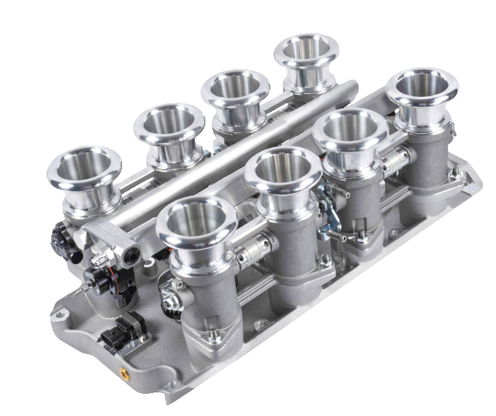
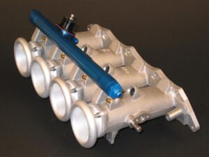
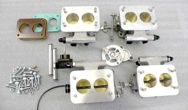
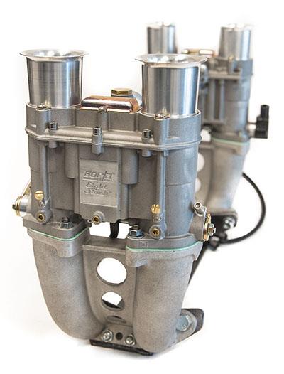
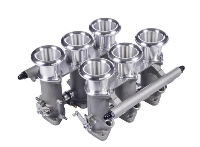
2000 Series Instructions

Click here to download these instructions in PDF format


Engine Preparation

  • Borla Induction recommends that you take pictures of the following items before you start the disassembly of your existing throttle system:
     - Fuel line locations
     - Sensor positions and wiring looms (injectors, sensors, etc)
     - Breather hoses, idle air plumbing and vacuum hoses
     
  • Label all sensors and applicable wiring with painters tape and a permanent marker. The following are common examples:
     - TPS sensor
     - Air temp sensor
     - MAP sensor
     - Idle Air Circuit (IAC)
     - Barometric pressure sensor (BARO)
     
  • Label all vacuum lines and their position relative to the throttle plate (pre or post throttle plate). These may include the following:
     - Brake booster
     - Evaporative emissions systems (charcoal canister)
     - Distributor advance vacuum
     - Crankcase breather
     
  • Start by removing the labeled vacuum and electrical lines from your old system.
     
  • Remove the air box, intake tubes and/or other ancillaries that fed the existing throttle body.
     
  • Carefully remove the fuel lines leading to and exiting the fuel rail. Use extreme caution as most fuel rails will have residual pressure in the line.
     
  • Drain the engine coolant (optional). If your existing intake manifold has a coolant passageway for preheating or has the thermostat outlet built in, you will need to drain the engine coolant to prevent spillage.
     
  • Start to loosen the intake mounting bolts or studs. Penetrating lubricant may be useful in loosening stubborn nuts and bolts. We recommend you remove all the bolts and studs.
     
  • Clean any old gasket material off the cylinder head intake surface. If necessary use a gasket scraper and some brake cleaner. Be careful not to gouge the machined surface as this will lead to undesired leakage.
     
  • In some installations shorter studs will be needed to allow for clearance to bosses on intake manifold. Test fit manifold to the head to insure the stock studs will suffice. If shortened studs are required we recommend using ARP stainless accessory studs. These studs feature a broached internal hex on one end making installation and removal a snap. They also are supplied with reduced hex 12 point nuts and ground finished washers.

  • To insure the ports on the manifold line-up with the head, place a new intake gasket on the cylinder head. Use two bolts or studs to insure alignment between both head and the gasket. Use a Sharpie pen to outline the material that needs to be removed. If material needs to be removed use a carbide burr or sanding drum and a die grinder. If you do not feel comfortable porting the manifold and head, please consult your engine builder. Borla Induction will not be held responsible for mistakes caused by improper port matching.


Intake Preparation

  • If you purchased a Borla Induction throttle system without injectors, now is the time to install them.
     
  • Note: Some new Borla Induction manifolds now use stock Honda injectors as well as RC modified Honda injectors. Although the manifolds are identical, the fuel rails differ in design. Milled between number 2 and 3 injectors on the fuel is correct injector type. Do not try and mix injectors with the improper fuel rail.

  • When installing new injectors, place a drop of oil on each o-ring to help ease assembly into the fuel rail and manifold.

  • If using circlips to hold the fuel injector in the rail, insert the clip on the injector first, align the circlips so they fall flush with the flat surface on the rail. Once the injector is seated, rotate the circlips ninety degrees. This will provide a positive lock to withhold the injector.
     
  • The stock style injectors do not use the retaining clips and are constrained in the fuel rail by the shoulders on the injectors. At the manifold end of the injector, an adapter is fitted to accommodate the dimensional difference between the stock injectors and the manifold.

  • A Borla Induction fuel pressure regulator is supplied with each 2000 series kit. The 2000 series fuel rails use a special Borla Induction regulator with a O-ring boss milled on the surface. Do not try and adapt another brand of fuel pressure regulator to a 2000 series fuel rail as this may lead to leakage and hence fire danger. If you need to remove the fuel pressure regulator use a small amount of oil to lubricate the O-ring before installing the regulator. Apply a small amount of blue Loctite® to the socket head cap screws (shcs) before tightening. Insure the -6AN outlet fitting is also tight at this point.

  • Once all the injectors are secured in the rail and the fuel pressure regulator has been installed, carefully slide the injectors into the pockets in the manifold. Gently rocking the injectors may aid in compressing the o-ring to slip into the pocket. When using stock injectors, insure the rubber adapter is in place.
  • Apply a small drop of blue Loctite® on each of the four socket head, rail mounting screws before inserting them through the fuel rail. Tighten the four socket head cap screws affixing the fuel rail to the manifold.


Installation

  • Once the head and manifold ports are matched, insure both surfaces are thoroughly cleaned and free of burrs and debris.
     
  • Start by installing the studs into the head. (If using bolts, proceed to the next step.)

    1. Place a new intake gasket over the locating studs in the head. If using bolts, we recommend using two dowel pins that may be pulled out once the manifold and gasket are properly aligned with the head.

    2. On some installations you may need to remove the linkage plate to gain access to the nuts (if using studs) or the head of the bolt.

    3. Hand tighten each of the bolts/nuts and verify the manifold and gasket are in their proper places.

    4. Torque the bolts/nuts to manufactures specs in the correct pattern.

    5. If the linkage plate was removed, reinstall the linkage plate. Use a drop of blue Loctite® on each of the 10-32 screws before tightening.

6. Route the throttle cable to the linkage plate assuring there are no tight bends in the path.

7. Insert the cable through the adjustment nut and place the barrel in the bellcrank.

8. Adjust the cable housing to tension the inner cable.

9. Adjust the throttle cable tension so that when the engine is hot, there still is a small amount of free play. Improper adjustment will usually lead to a high idle once the engine has reached operating temp. This is due to the natural thermal expansion of the linkage plate that takes up some slack in the line.


Tuning/Sensor Installation

1. Once the ITB kit has been installed several steps are necessary to insure proper function.

2. The throttle cable tension is the first adjustment which was performed in the previous installation step.

3. Reattach the water heater and/or water outlet lines to the manifold if applicable that were disconnected in the removal of the stock intake manifold.

4. The map sensor should be attached to the vacuum accumulator manifold. This varies from kit to kit. Early kits have an external billet accumulator located between the fuel rail and air horn flange with barbed ends. Later kits have a cast in accumulator with tapped or barbed ends.

5. The air temp sensor, if applicable may be installed on the boss provided using the stock hardware originally removed from the stock manifold.

6. The TPS sensor may be plugged in. It will be necessary depending on the ecu used to cut the existing plug off and recrimp with a 3 pin mini timer plug as supplied by Borla Induction. Refer to the drawing on the right for the correct pin assignments.

7. The fuel system plumbing is critical to the proper fuel delivery to the engine. Borla Induction only recommends the use of high quality AN plumbing from a respected manufacture. The Borla Induction regulator is a bypass style regulator capable of metering 300 L/hr @ 3 bar of fuel pressure. There is only one proper way to plumb the system for proper metering. The fuel inlet on 2000 series kits is located on the opposite side of the fuel rail as the regulator. The bypass exit is the single outlet from the regulator. Do not plumb the fuel rail with the inlet closest to the regulator, this will cause a slight pressure drop to the last cylinder which can adversely affect performance.

8. -6AN line is recommended for the supply and return lines to the fuel rail. If you are unfamiliar with AN plumbing and the proper techniques to assemble the fittings, please consult your engine builder or race supply shop. If any of the conical sealing surfaces are damaged in installation or removal, toss the old fitting the replace with a new fitting. Leaky fittings and poor connections are a serious cause of engine fires.

9. The next step is to set the idle stop screw. The screw setting is set at Borla Induction for approximately 1100 rpm. However, due the nature of racing engines with high lift/duration cams, adjustment of the idle is not uncommon. The idle screw is adjusted my loosening the nut that secures the setscrew, and then using a hex wrench, adjusting the setscrew in for increased idle speed and out for decreased idle speed. Once the required idle speed has been reached, retighten the nut to prevent the screw from moving.

10. The Wide Open Throttle (WOT) setting is set at Borla Induction and should not be adjusted. The WOT setting insures the throttle plate is parallel to the flow through the throttle body for maximum flow.

11. Periodically the throttle cable will need to be adjusted to remove excess slack from the cable. In addition, if you notice the throttles stick when the engine is hot, you may not have enough clearance. All adjustments made to the 2000 series should be done at operating temperatures.

12. The individual adjusters between the throttle levers are factory set. These hex pieces are precisely set at Borla Induction so every throttle plate opens synchronously. Any deviation from this adjustment will yield uneven balance between throttle bores. If for some reason these need to be adjusted, the unit is best returned to Borla Induction who will adjust it at no charge.


DISCLAIMER:

Most of the parts sold by Borla Induction are designed, manufactured, and sold for racing purposes only. This means that they should never be used on a public highway on any vehicle originally equipped with emission controls. Borla Induction does not condone the removal of any emission control device.